
This page is dedicated to anyone ( but especially the technically minded ) interested in knowing how this engine was made.
See disclaimer.
Siehe Haftungsausschluss.


Click on the enlargement button ( move mouse to middle of picture ) to get a closer, more detailed look at the pictures and sketches. To get back to regular size, press the Escape button
on your keyboard.
Intro
First of all thanks for your interest in my Stirling Model. I say `` my model ´´ because it is my own design, and not a copy of someone else´s. The entire concept of the
engine is based on one question that I asked myself quite some time ago. `` If I were to build a stirling model just for myself, how would I want it to look and work ?. ´´ The answer was,
`` An optically interesting model which I could run at approx. 300 - 400 rpm´s. ´´
A few people have asked me, `` Why so slow ? You could do this or that and make it faster and more powerful. ´´ Sure I could, but that´s not what I´m looking for.
I´ve seen Stirling Models that have been clocked at 1400 rpm´s. You can´t see any details of the working parts, only a blurr. I´ve also seen models runnig about 40 rpm´s. Kinda boring.
At 300 - 400 rpm´s you can still see details of movement without falling asleep. So if you are looking for speed or power, this is definitely not a model for you. If, on the other
hand, you are interested in a machine that is interesting in both statik and dynamic states ( a fun machine ), then you might want to keep reading.
Rights
There are no Patents, Copyrights, Design Rights or anything of this nature on this Stirling Model and there won´t be in the future. Then by International law, anything presented to the general
public before Patents, Copyrights and the like have been applied for cannot be granted said rights. And since this Model has been presented in the `` You Tube ´´, well you can´t get much
more public than that. So this one is Free To All. I have no objections of anyone copying this model. But if you do, please be aware of the following:
I´ve added enough pictures, technical drawings and comments here to help anyone to be able to understand how I made this model. The decription, however, of how I did it is not a
recommendation that you use the same working methods that I use. Please use your own discretion and methods of machining and read the disclaimer at the end of this writing.
I have no objections of anyone downloading pictures, technical drawings or texts from this Website as long as they are for your own personal use. I only ask
that you do not change them in any way or spread them around ( especially through the internet ). Thanks for your understanding. Dave ( See " Copying The Prints " )
Measurements
Apologies to all of you who are using the English System, but I live in Germany and all my machines are based on the Metric System. So all the parts and technical drawings are based on and given
in Millimeters ( abbreviation = mm ).
Tolerances
None of the drawings have tolerance specifications. The general tolerances I used for most of the machined parts of the Model are plus / minus 0.1 mm ( one Tenth of a Millimeter ),
and a lot of those parts don´t actually require such close tolerances. But by considering the function of the part in question, a practiced machinist can usually decide what tolerance range
could or should be used. When in doubt, just use the smallest Tolerances your machines can manage. There are, of course, exceptions like the fit between Power Cylinder and Piston, but I´ll talk
about them as we go through the different drawings. For other tolerances, such as the spacings between the columns, you can use the Scales that I have added to the drawings. They are fairly
accurate.
The Technical
Drawings
I know I´ve broken a lot of rules making these drawings, but it was never my intention to make perfect sketches by the book. My only goal was to make them understandable without getting
bogged down in detail.
Threads
For those who are not familiar with Metric Thread Specifications, here a few infos:
All thread specifications in the sketches are given starting with the capital Letter M for Metric. Example 1: M38 X 1 Example 2:
M10
The first example is an example of a Non-Standard-Thread, which is always specified by the letter M followed by the nominal size ( 38 ) followed by X followed by the pitch
( 1 ) in mm.
In the second example ( M10 ) only the nominal size is given, the pitch is not. This specifies Standard Thread. Hier are the pitches of a few Standard Metric
Threads.
Nominal Size Pitch
M3 0.5
M4 0.7
M5 0.8
M6 1
M8 1.25
M10 1.5
M12 1.75
M16 2
For the Tap Drill Sizes for all Metric Standard and Non-Standard-Threads use the following formula: Nominal Size minus Pitch = Tap-Drill-Size.
Example 1: 38 - 1 = 37 mm
Example 2: 10 - 1.5 = 8.5 mm
So
Let´s Get Started
I´ll now go through the Pics & Sketches and comment on the things I think would help to understand the structual, constructional and or functional aspects of the parts represented by the
drawings.
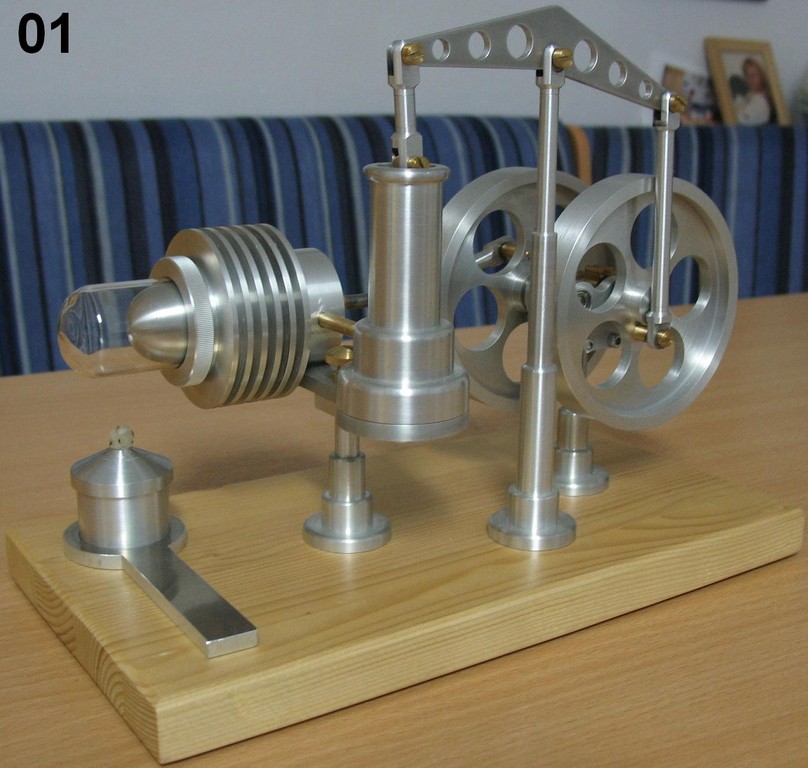
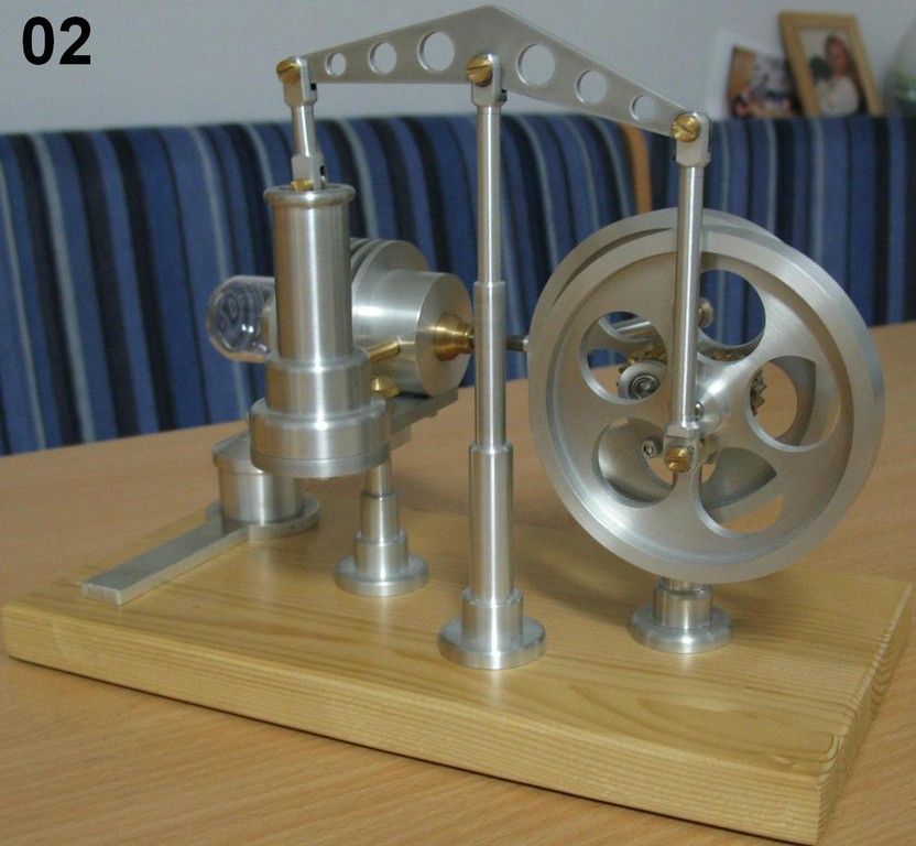
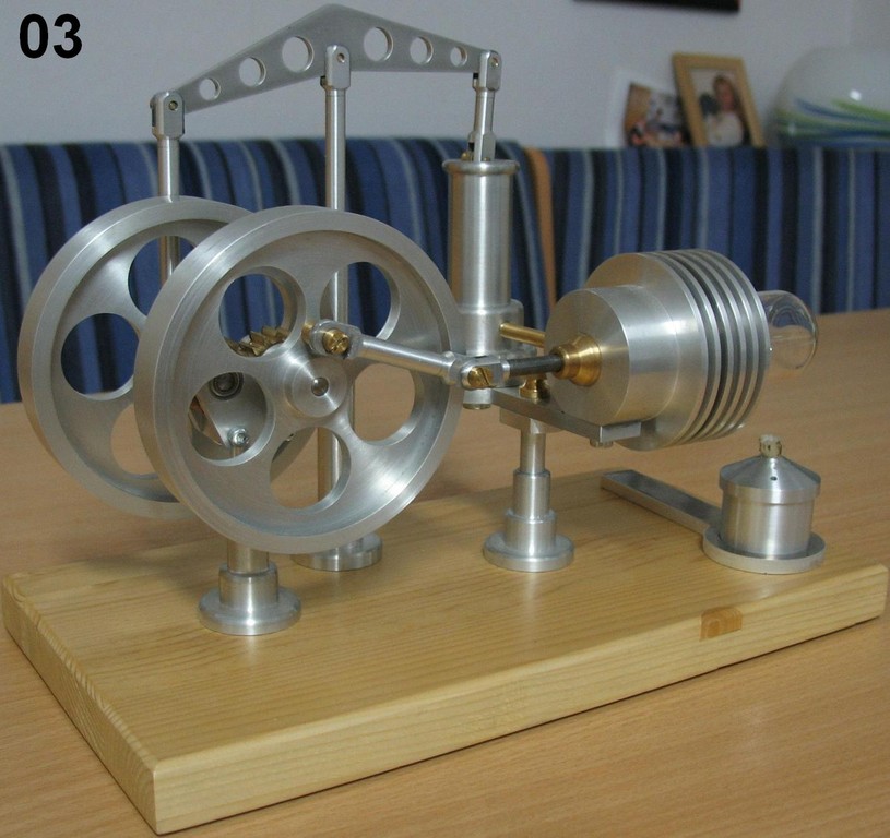
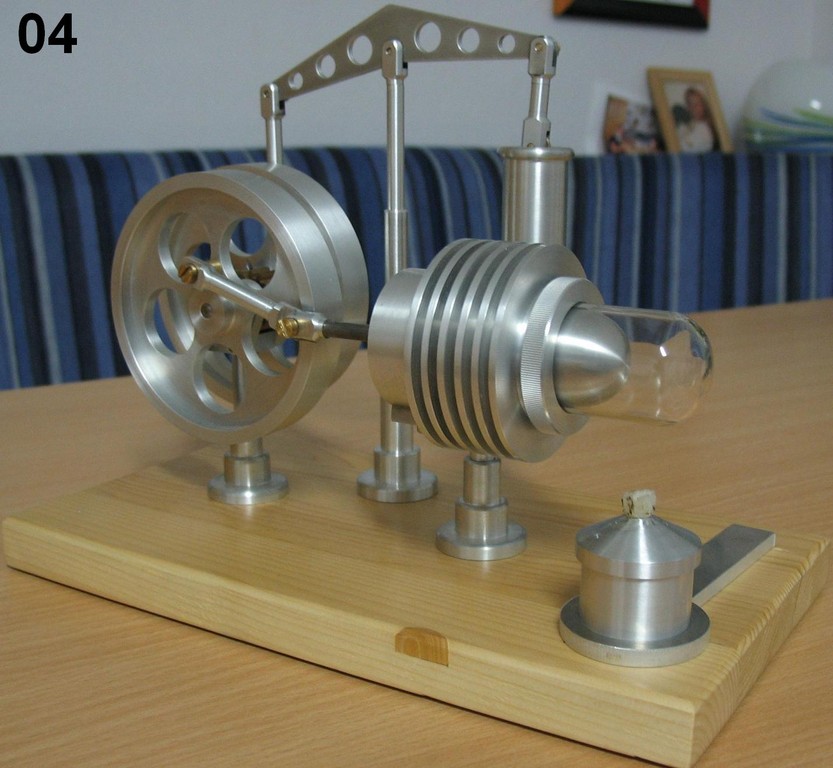
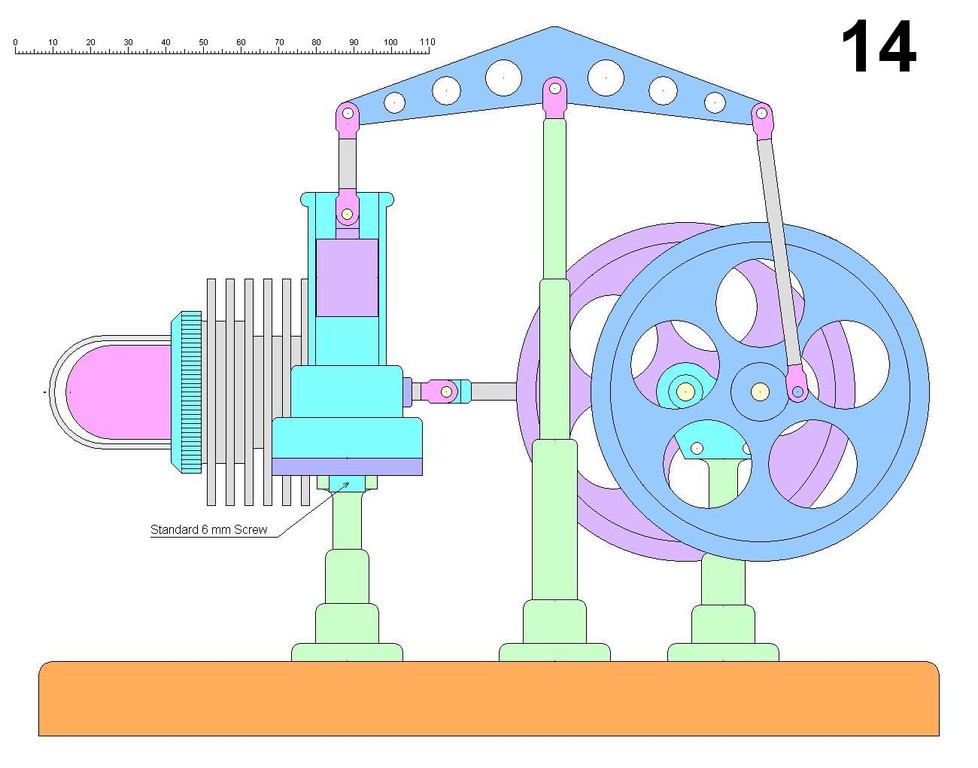
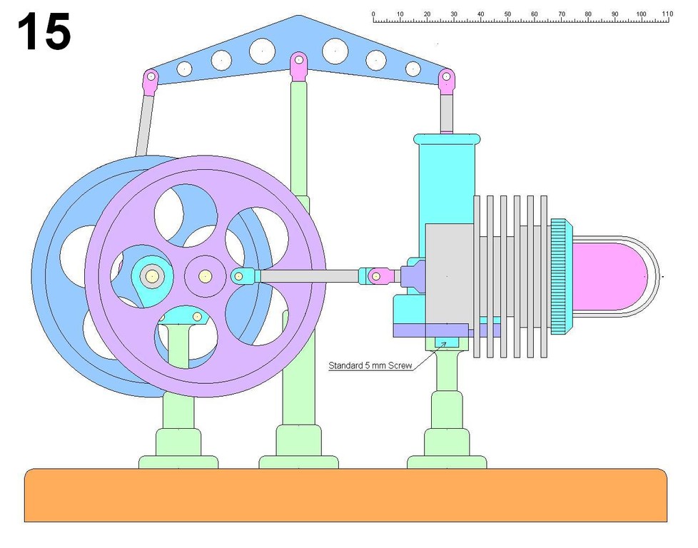
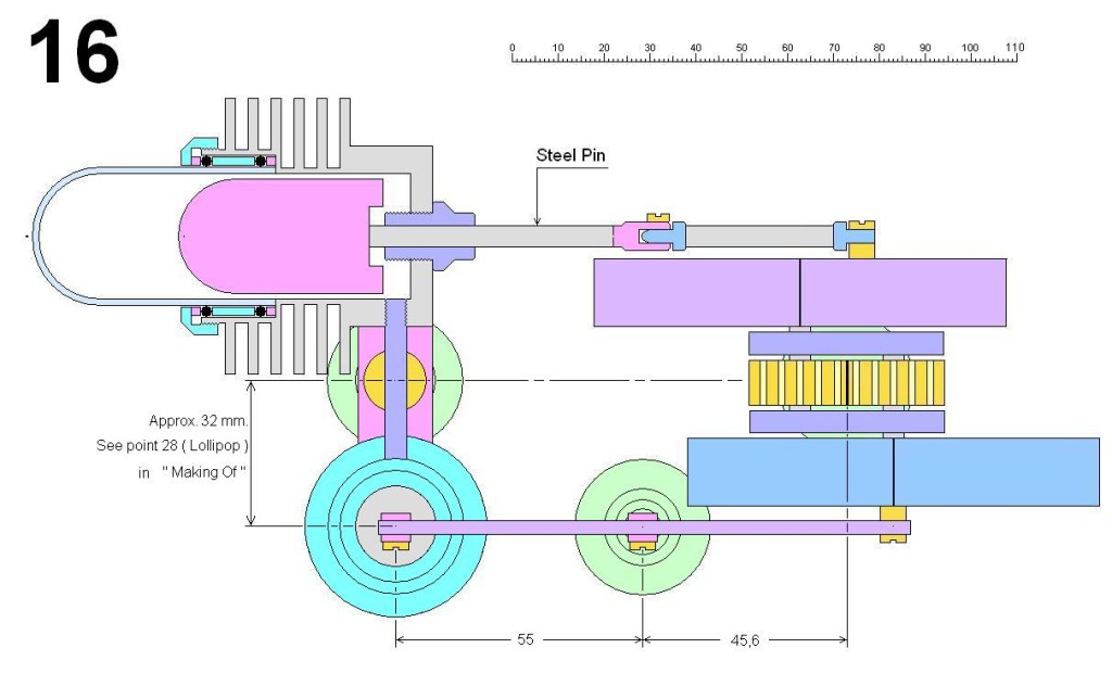
The first Pics & Sketches ( 1 -16 ) should give you a good overall idea of how the machine is constructed. I´ll be refering to some of them as we go through the other drawings.
Tipp: You can enlarge the pictures by just klicking on them. Scroll to leave enlargement.
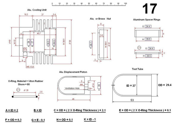
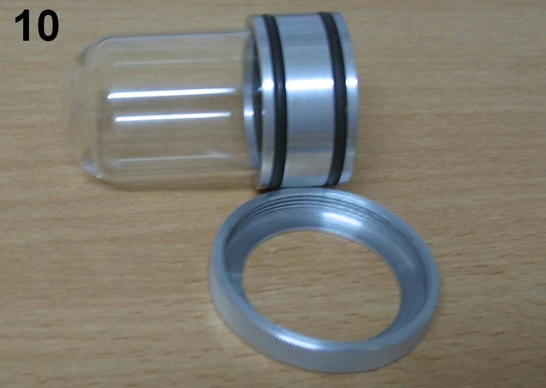
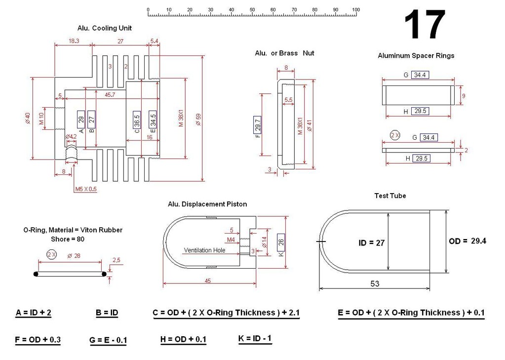
Nr. 17
Displacement Assembly
All of the dimensions framed in little boxes will be dependant on the size of the Test Tube and the O-rings being used. I got my tube from Ebay, and I have no idea where it came from originally.
So the formulas at the bottom of the sketches must be used to calculate the necessary dimensions for other tube sizes. If the tubes to be used are significantly larger or smaller than the one I
used it may be necessary to adjust the dimensions of the power cylinder. If so, then go by the volume displacement- and not the diameter differences.
If the O-rings to be used have to be stretched a lot ( not recommended, ideally the O-rings should be 1-2 mm smaller in diameter than the test tube ) to get them over the tubes, they will
decrease in thickness. So dimension E may also have to be adjusted to accommodate this. Here´s what I did. I stretched the O-rings over the glass. Then, using a Vernier Caliper, took a
measurement of the outside diameter of the O-rings and added one tenth of a mm.
The aluminum cooling unit will be the most difficult and time consuming part to make. Most critical is cutting the gaps between the cooling fins. Aluminum tends to build up on a cutting edge
greatly increasing the cutting resistance. If there is slack in the cross support this increased resistance may even come to a point where the slack is drawn out of the cross support
causing the cutting tool to be pulled suddenly into the Aluminum causing a gashing or gouging effect and ending up braking the cutting tool and damaging the cooling unit. My tipps:
1.) Adjusting the height of the cutting tool to a little above center helps prevent it from being
suddelny drawn into the cooling unit ( this is no guaranty, but it should help ).
2.) I Use a cutting fluid. Better still, is using lots of it.
3.) I draw the cutting tool frequently out of the cutting material and check for and remove build-up.
4.) Trying another material for the cooler like brass or bronze would greatly reduce the danger of
gouging.
If Aluminum is used for cooler and the nut, keep this in mind. Aluminum rubbing against Aluminum, especially in a dry state ( and especially thread ), has a tendancy of galling. What is galling ?
It´s like this. When the two aluminum parts rub against each other ( again especially in a dry state ) the peaks of the microscopic unevenness start to tear and roll around ( in this case )
in the gap between the inside and outside threads and begin gouging into neighboring peaks. When this effect snowballs and produces chips larger than the gaps between the threads, the movement of
the threads will become blocked. Usually at this state there is no more going forward and also no more going back. One can try ( hoping against hope ) using spray-oils to help loosen things up
again, but usually it is all too late, and the result is that the two parts will have to be made again. So always make sure:
1.) that the surface quality of the threads are as good as you can get them.
2.) to coat the thread surfaces with oil before using ( thick oil is better than thin ). Be careful not to get
any oil on the O-Rings.
3.) to cut these two threads liberally to avoid a tight fit.
I´ve also considered using Brass or Bronze for the nut ( I have never experienced galling between Aluminum and Brass or Aluminum and Bronze ).
The O-rings I use are made of Viton Rubber. This material has very good chemical- and heat resistance qualities, and after running the motor about 40 or 50 times there is not the least sign
of melting or any other damage to the rings.
The Shore Value ( Shore = 80 ) is the specification of how soft ( or hard ) the rubber is. I assume Shore 80 is a spec that is commonly used in a variety of applications, and works just
fine.
If oil gets on the O-rings they may not be able to hold the glass heating unit ( test tube ) in place. Mine just popped out one day traveling about 8 inches in the air before ending up making a
beautiful brown to black burn mark on one of my wife´s kitchen towels. So it´s very important to keep the O-rings and all parts that come in contact with them absolutely free of oil, grease and
the like.
I decided to hollow out the Aluminum displacement piston to make it lighter saving wear on the Bronze Bushing. In order to achive this I made it out of two segments ( slightly larger in outside
diameter than the final tolerance ) connecting them with thread. After hollowing and connecting them together with a thread sealant, I made the last cut. You can´t even see where the two parts
are connected. I added a ventilation hole to prevent pressure build-up.
For cutting the test tube to its final length I wrapped it in a soft piece of neoprene rubber and chucked it up ( very lightly ) in the lathe. Running the lathe at a rather low speed I used a
Dremel - Tool with a Diamond - Wheel to make the cut. After this preliminary cut I then used the Dremel again ( this time with a fine sanding disc ) to smooth up and round off the jagged
edge.
These two processes require a very light hand with `` feeling ´´. I cannot ( for safety reasons ) recommend this method of cutting the test tubes. I only offer here a description of how I
do this operation. It would be much better if a qualified glass cutter were to make this cut. Or maybe someone who works in a chemistry lab?
I use a vacuum cleaner to suck up the glass dust generated in this process being very careful to position the dremel so as to direct the dust directly into the vacuum cleaner nozzle. I also use a
dust mask just in case any of the dust gets by the vacuum cleaner. Safety glasses are always a must for any type of work ( see disclaimer ).
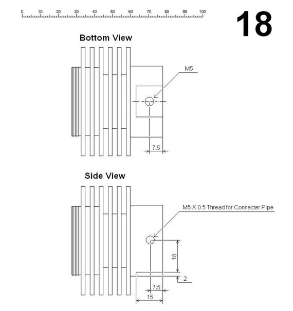
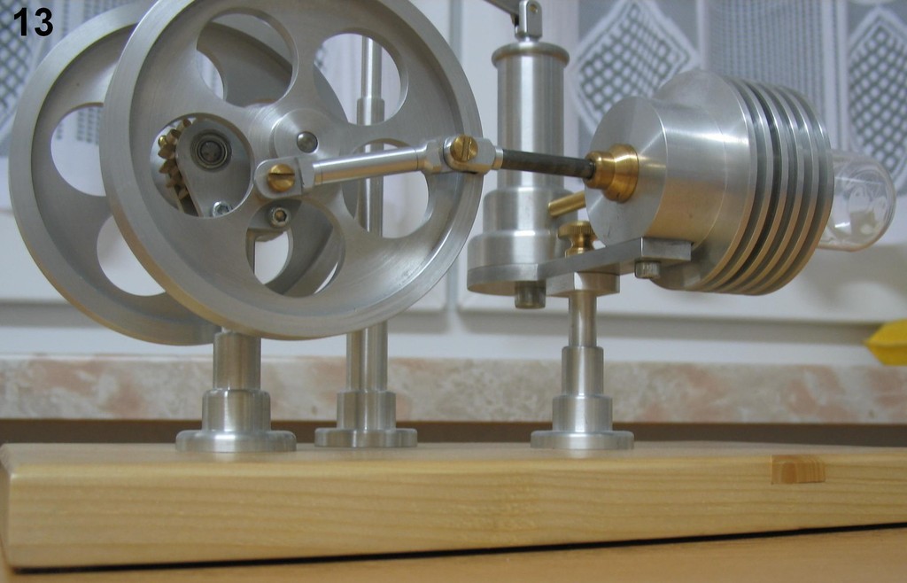
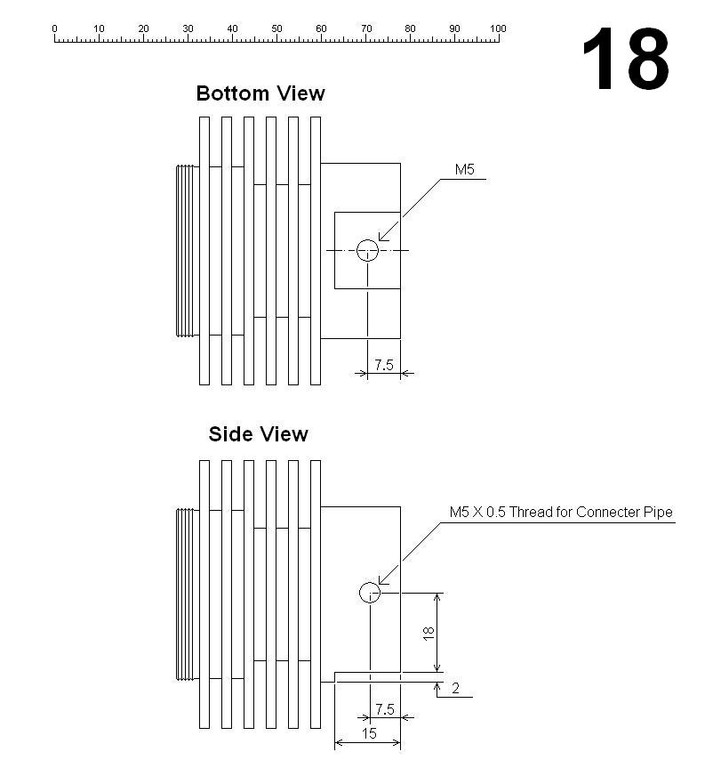
Nr. 18 Cooling
Unit
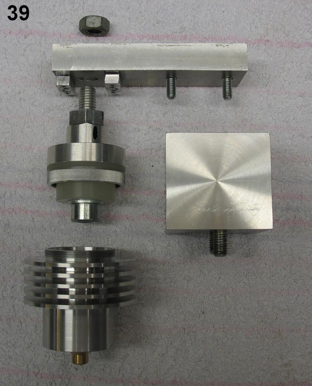
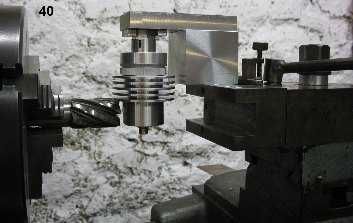
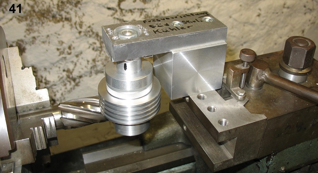
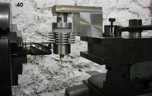
As you can see in this drawing I milled the base of the Cooler 2 mm to accomodate it´s mounting on the part I call the Lollipop ( see also Pic Nr. 13 ). Because I don´t have a milling machine I
do all my milling on the Lathe. Pics 39, 40 and 41 show how I did this. More about milling on the lathe later.


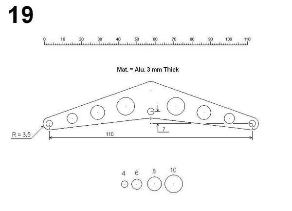
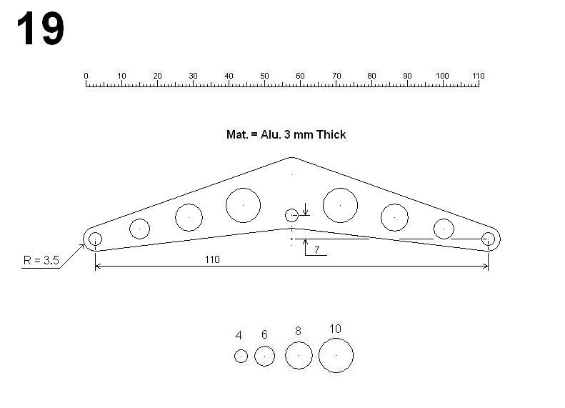
Nr. 19 Balance Arm
You can see in a lot of the pics how the arm is used in collaboration with the connectors. The diameters of the different holes are given below the main sketch. The distance between the two 4 mm
holes ( far left and far right ) is exactly 110 mm ( see scale ). For the placement of the other holes I kinda played it by ear.
For all of the holes in this part I used Reamers instead of just Regular Drill Bits for two reasons.
1.) Reamers deliver very exact tolerances, and
2.) they also produce very good surface quality results eliminating the eventual extra work of `` cleaning up ´´ the rather messy results that Regular Bits tend to
make especially when working with thin materials.
When using Reamers ( for example the 6 mm hole ) drill first using a Regular Bit of about 5.6 - 5.7 mm leaving 0.3 - 0.4 mm for the Reamer to cut. Use lowest cutting speed possible and cutting
fluid for Reamers ( they are expensive and easy to damage ). I have a drill press that I have modified to run at 64 RPMs which is ideal.

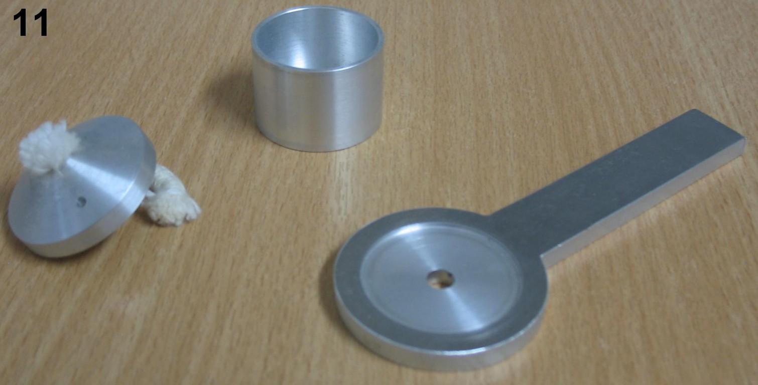
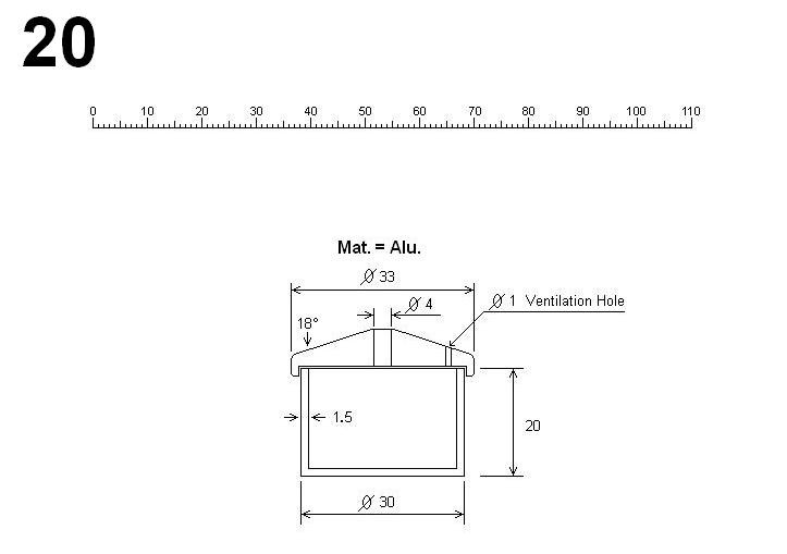
Nr. 20 Burner
The wicks I found were about 5 mm thick, so I made the wick hole 4 mm. This turned out to be ideal allowing easy adjustment of the wick height without a choking effect ( restricting the flow of
the fuel ).
I use only high grade denatured alcohol ( Ethanol, 96% ). It burns clean and hot enough to run the machine without damage to the O-rings. I have no experience with other fuels.
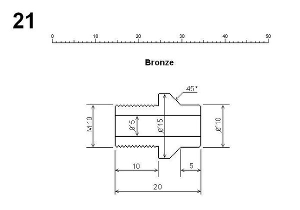
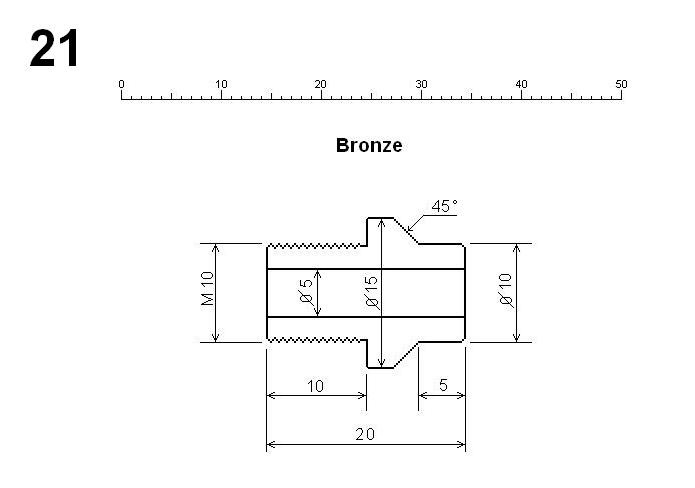
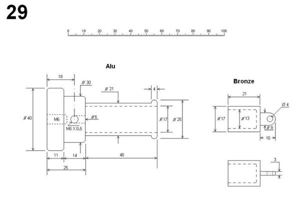
Nr. 21 Bushing
I used Bronze for this part because if it´s Low Friction and High Wear Resistant qualities, but Brass would also be OK. The tolerance between the 5mm hole in the bushing and the steel pin going
through it should be the finest that is possible. Remember, the main principle of a Stirling Engine is that of a closed ( airtight ) system. So the gap between
the pin and the bushing has to be enough to allow a slip fit, but at the same time guaranty that a slight oil film is enough to prevent air leakage. Here is how I did it.
The steel pin I use is a ( store bought ) standard unhardened pin typically used in the Machine Construction industry. These types of pins are precision ground to very fine tolerances and have a
very fine surface quality. Using a reamer for drilling the hole for the pin usually results in a slight Press Fit. But by running the reamer back through the bushing combined with very
slight radial pressure ( pressing the inside wall of the bushing against the cuttung blades of the reamer ) and at the same time rotating the bushing to insure uniform results, sooner or later a
Slip Fit will result. Time and patience will pay off on this one.
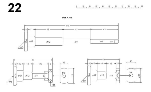
Nr. 22 Columns
To make the turning of the columns a little easier I made all of them in 2 Parts separated at the conjunction of the 8mm and 12mm Diameters connecting them with M6 thread. The lengths of the
individual segments are not that critical. The full lengths of the 2 smaller columns ( 60 mm and 49 mm ) are important to insure that the heights of the centers of the flywheels and cooling
unit are identical.
All of the columns have an inner thread M6 at the center of the base to accomodate mounting on the Base Board
Again I did the milling on the Lathe. More about this later.
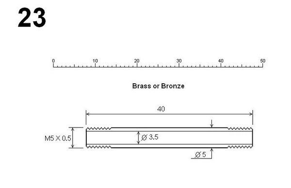
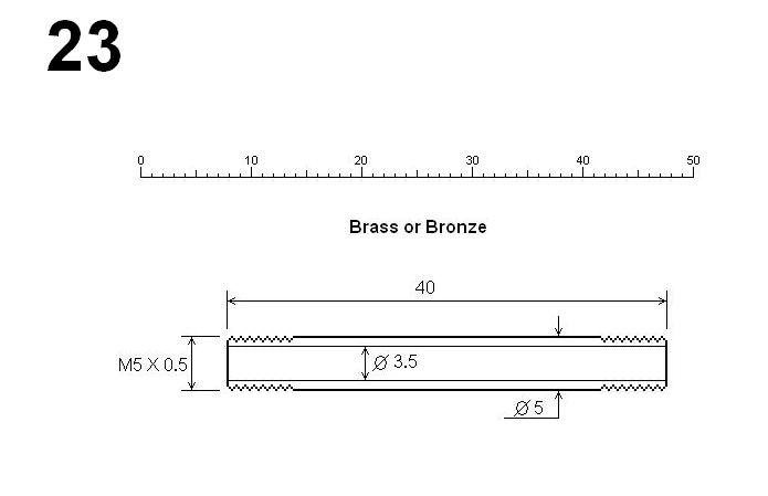
23 Connector Pipe
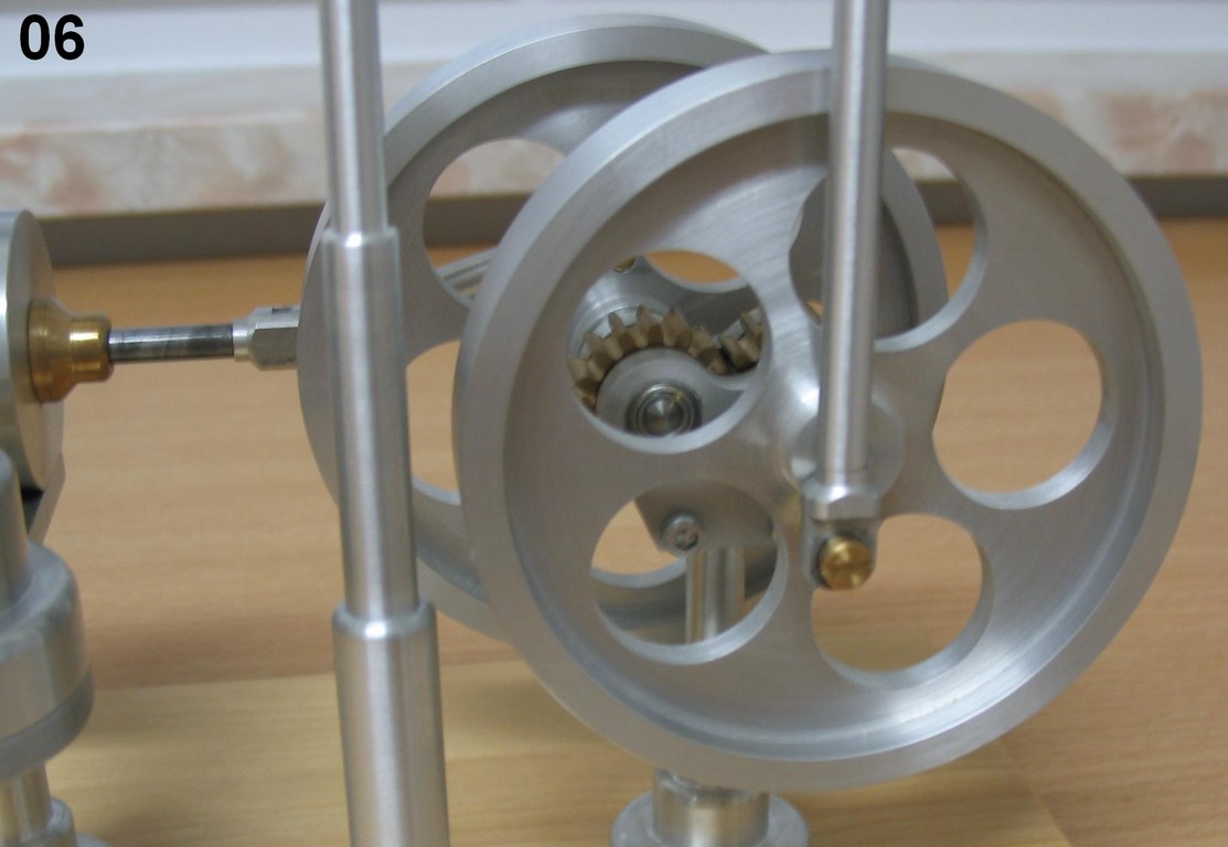
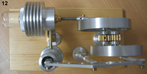
This is the part that connects the Coolung Unit to the Power Cylinder ( see Pic Nr. 12 left ). If I had to design this part again, I would make it bigger ( larger in
diameter ).
I used a thread sealant with this part to insure an airtight connection.

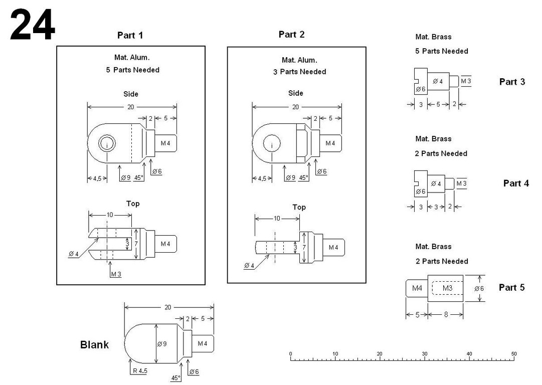
24 Connectors
In order to make the Parts 1 and 2, eight of the Blanks shown at bottom left are needed. These Blanks are then later held in place by their threads when milling. More about this later
when we get to the theme `` Milling On The Lathe ´´.
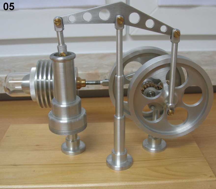
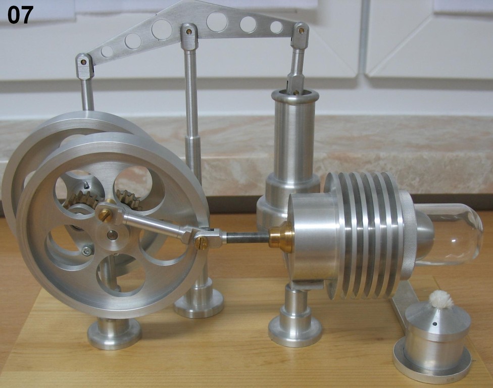
Pics 5 and 7 give you a good view of how the connectors work together. The Gaps in Part 1 should be at least 0.1 mm wider than the Tongues of Part 2 to insure a slip fit. For the same reason the
Lengths of the 4 mm Diameter Segments of Parts 3 and 4 should be at least 0.2 mm longer. If any of these parts get pinched by tightening the screws, it can ( and probably will ) prevent the
machine from running.
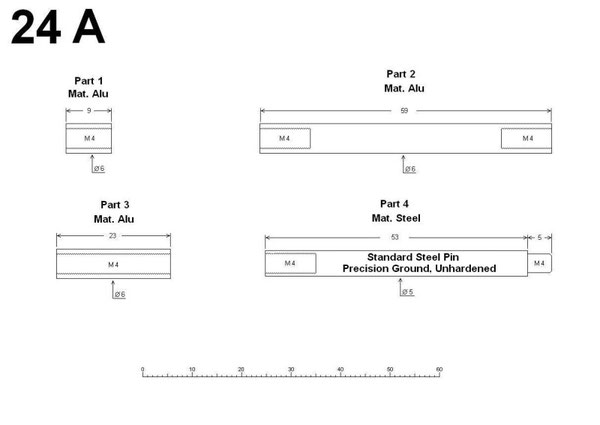
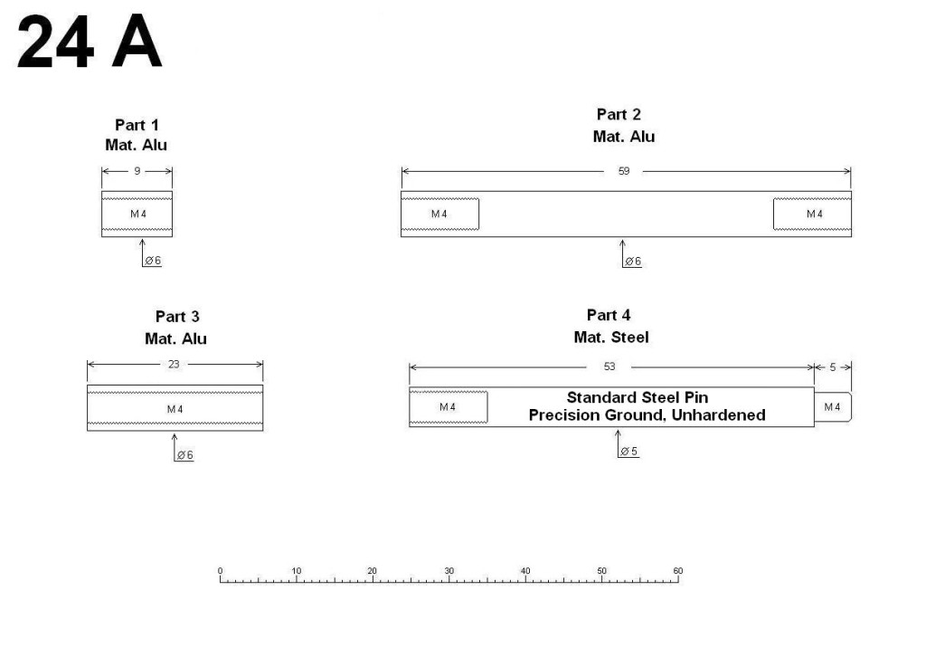
Many Thanks to Norbert for pointing out to me that I had forgotten the sketches for the 4 Connector Rods. Part 1 is the one between the Balance Arm ( Walking Beam ) and the Power Piston, Part 2 from Balance Arm to Flywheel. Both of these are best seen in Sketch 14.
Parts 3 and 4 are seen in Sketch 16.
Depending on the outcome of the Connectors in Sketch 24 you may have to vary the lengths of the Rods slightly.
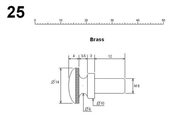
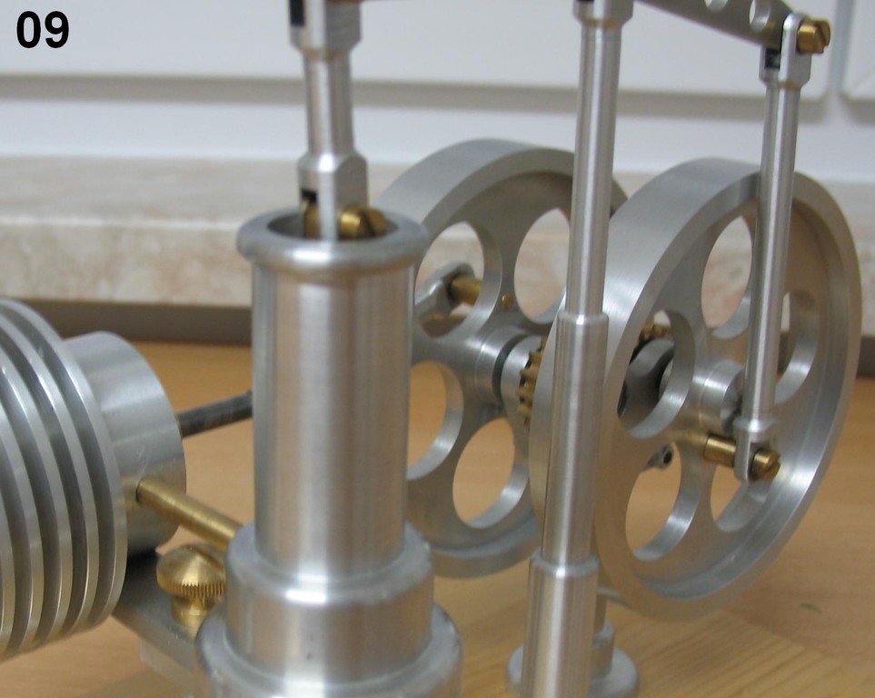
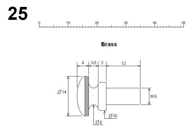
25
Fastening Screw
Pics 9 and 13 give you the best views of this part. A standard screw would have done for this one, but a decorative screw ( I think ) looks much better. I put a slot on top to accommodate a large
screw driver, but if I had to make it again , I´d mill a hexagon at the 10 mm diameter section and use a wrench.
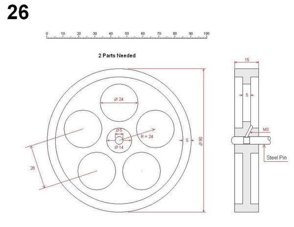
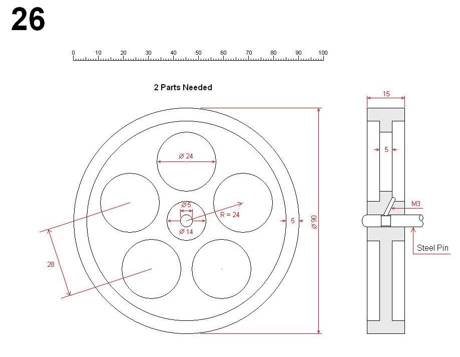
26 Flywheel
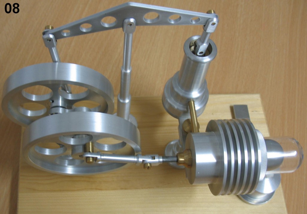
The Flywheel is mounted on a Steel Pin as described earlier in the section `` Bushing ´´, and also has a Slip Fit made in the same way. It is held in place by an M3 Set Screw ( visible in
Pics 7 and 8 ). I turned down the diameter of the shaft where it meets the set screw about 0.4 mm. If not, the deformation caused by the set screw will turn the Slip Fit into a Press Fit, and you
will have problems dismounting and or adjusting the wheel.
The five 24 mm diameter holes were all turned on the lathe instead of just drilled. Why ? An ordinary drill just won´t deliver the surface quality this part deserves, and a 24 mm Reamer is just
too expensive for my money.So I improvised and made a jig. More about this later.
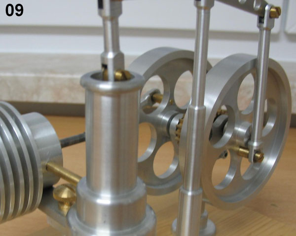
In Sketch 09 you can see how Part 5 ( two Pieces ) of Sketch 24 are connected to the Flywheels.
The Distance of Part 5 from the center of the Flywheel on the Balance Arm side is 10,5 mm which will give the Power Piston a Stroke of 21 mm.
The Distance of Part 5 from the center of the Flywheel on the Cooler side is 13,5 mm which will give the Displacement Piston a Stroke of 27 mm.
These two Strokes are calculated from Volume Displacement Factors and are very important for the Function of the Motor.
I would like to apologise for inadvertantly leaving this information out for so long.
Dave
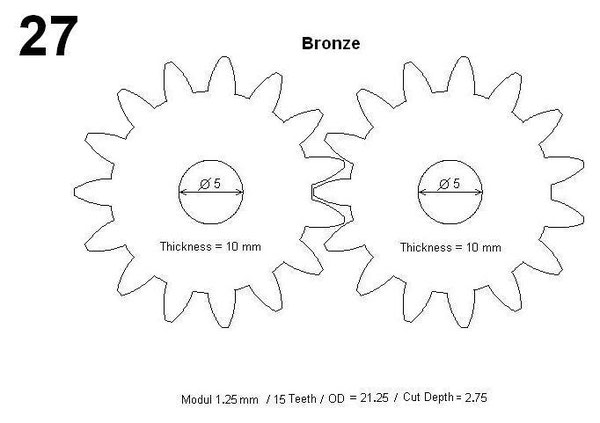
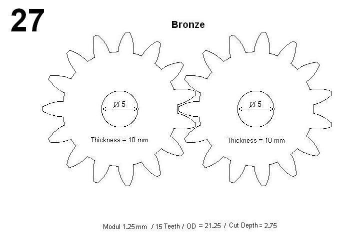
27 Gears
Pic 12 gives you a good view of the two interlocking gears. As you can see in the gear on the left they are fixed to the shaft with set screws. So a slip fit as with the Bushing and the Flywheel
is needed. And the shaft must be turned down as described in the section `` Flywheel ´´.
The gears I use are Metric using the Module System and not the English / American Diametral Pitch System. So depending on which gears end up being used the demensions of the Shaft Plate in
Sketch 30 will have to be adjusted. I used Bronze on these gears, but Brass is also OK.
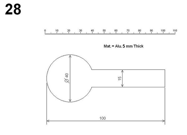
28 Lollipop
This is the part used to connect the Cooling Unit and the Power Cylinder to their corresponding Column. I purposely made it a little longer than needed and cut off the excess during the
assembly. The final length was 93.4 mm.
IMPORTANT: ASSEMBLY OF THE TRANSMISSION MUST BE MADE BEFORE CALCULATING THE DISTANCES NEEDED BETWEEN THE COOLING UNIT AND THE POWER CYLINDER !!!! THE REASON FOR THIS IS THAT THE
TRANSMISSION ASSEMBLY IS A LITTLE TRICKY AND MAY YIELD DIMENSIONS OTHER THAN THOSE WHICH HAVE BEEN PLANNED ON PAPER.
As you can see in some of the pics I had a left over Lollipop and use it as a base for the burner. In pic 11 you can see that I turned a small recess in it ( about 1 mm deep ) to keep the burner
in place.
29 Power Cylinder and
Piston
I think the sketch of the Power Cylinder is pretty much self explanatory. Don´t forget the 5mm hole in the center allowing air flow to the piston.
I hollowed out the piston to make it lighter. Bronze again my choice of material, but Brass will also do. Might be interesting trying plastics for this part. Teflon maybe ?
The fit between clyinder and piston is cirtical. Here my tips:
1.) I made the Cylinder first, giving the Surface Quality of the Inside Diameter absolut priority over the Diameter Size ( 17 mm ) using my sharpest cutting tool
slowest feed settings and lots of cutting fluid.
2.) When I made the piston, I initially cut an inside Thread M12 to have a way of fastening the part to an adapter for the Milling Work ( more about this later
). I cut the outside diameter leaving it about 0.03 mm larger than the Cylinder. Then I used fine sandpaper ( 600 emery cloth ) and a cutting fluid to make the
final fit. Time and patience are the key words here. Here´s a good test for the fit results:
A) Clean both ID of Cylinder and OD of Piston removing all traces of dirt and oil.
B) Insert the Piston into the Cylinder until the top of the Piston is even with the top of the Cylinder.
C) Pinch the hole for the Connector Pipe with your finger making it air tight.
D) Now let go of the Piston. If the fit is perfect, the Piston will actually swimm on air and will not sink. You can lightly tap and pull on it and let go and
it will act as if it were sitting on a spring bouncing up and down. But after removing your finger from the hole the Piston will drop immediately to the bottom of the Cylinder. I
don´t have Precision Instruments for measuring Inside Diameters but I would assume the Tolerance in this case to be less than one hundredth of a millimeter.

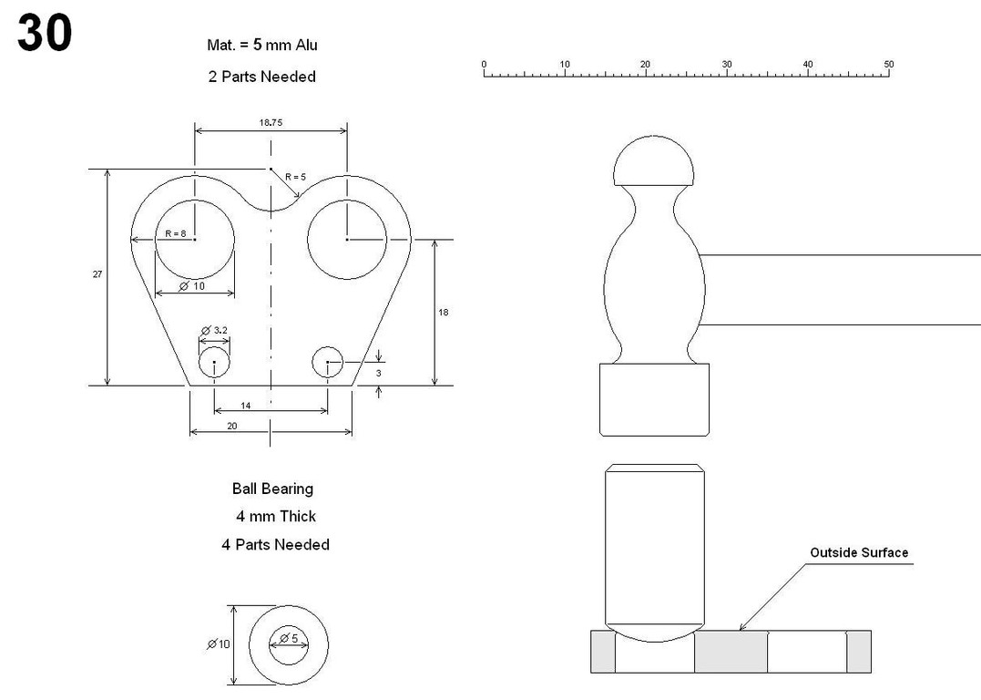
30 Shaft Plate
As stated earlier, depending on which gears are used, the demensions of the Shaft Plate will have to be adjusted accordingly.
To simplify the assembly of the Transmission I made a Slip Fit Between the Ball Bearings and the Shaft Plates as described earlier with the Bushing ( using a Reamer ) deburring only very
lightly. But then ( and here´s the trick ) I used a rounded steel pin ( see drawing ) and ( using light strokes ) hammered a slight deformation into the holes for the Bearings ( but only on the
Outside Surface ) until the deformation stopped the passing through of the Bearings. The result is that you can now ( easily ) assemble the transmission and at the same time prevent any left and
right wandering of the shafts.
The Ball Bearings I use are the sealed type which prevent dirt from getting inside, and the permanent lubrication from leaking out.
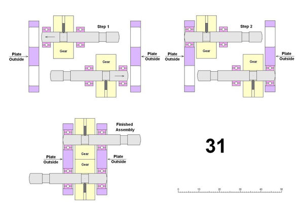
31 Transmission Assembly
Step 1: Using the pins I mentioned earlier in combination with standard bearings results in a press fit, which is what we want here. So press the Bearings onto the shafts in their
perspective positions remembering to place the Gears ( Gears have slip fits ) in between. Use shims as spacers insuring correct spacings. When pressing Bearings onto Shafts apply pressure
ONLY TO THE INNER RACE OF THE BEARING. Heating the Bearings and or Cooling the Shafts and a drop of oil will make this job a little easier. You may even want to polish up the shafts a little
using very fine emery cloth and cutting oil if you think the press fit is too tight.
Now insert the Bearings into the inside of the Plate Holes as shown in Step 1.
Step 2: Now push the two Plates towards each other inserting the other two Bearings into their perspective holes. Attach the Plates to the 60 mm Column with screws and tighten the
screws. The two Plates should now be exactly Parallel and the two shafts should rotate very easily. If not, you may ( for example ) have to use a vice to force the Plates into a parallel
position. Retighten the screws after adjusting the Plates. Maybe the gears are set too close to each other and are blocking the movement. Look for other reasons if something doesn´t seem
right.
There´s no use continuing on this Model until the Transmission fits and functions perfectly. So keep playing and adjusting until everything is right.
Now position and fasten the Flywheels and measure the complete width of the assembly and compare to your calculated width. Don´t worry if the two don´t coincide exactly. Just take these
differences in mind when calculating the distance between the Cooling Unit and Power Cylinder.

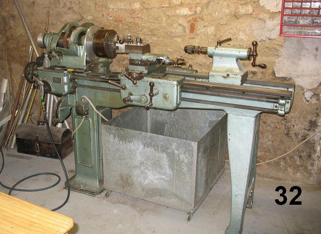
Milling On The Lathe
Pic 32 shows the lathe I bought in 1983 for about 250 dollars ( best investment I ever made ). It was manufactured in 1937 by the J. Gast Company in Berlin and had been standing unused in a
garage for I don´t know how long. So I took it apart and cleaned all the parts, oiled and greased them up againg and put it back together, and it´s been runing ever since.
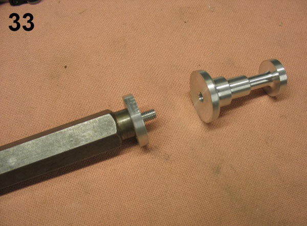
33 Adapter 01
For most of the milling work I used a piece of 19 mm steel hexagon stock and cut a 10 mm inside thread in it. Then I made adapters accordingly ( mostly out of Aluminum ) allowing the connection
between the Hex Stock and the parts to be milled ( in this case, the Column ). The Parts must be fastened very securely.
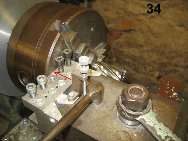
34 Squaring
The Tool Holder
I always do a Quick - Alignment by loosening the holder, pressing it against the face of the chuck ( see red Arrow ) and tightening again. This ( so far ) has been good enough for all practical
purposes. At first I was skeptical about this method. But after checking the results a number of times with a Dial Indicator, i was pleasantly surprised at the results.
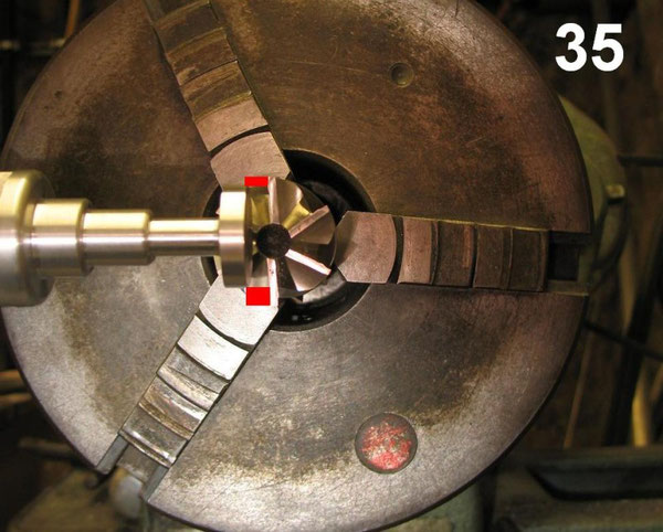
35 Adjusting The Height
After clamping the Hex - Stock in the Tool Holder I always make sure that the middle of the part to be milled is higher in elevation than the middle of the cutting tool ( 2 - 3 mm )
to help prevent the part being suddenly drawn into the cutting tool and taking too big of a bite. If this happens something will usually break.
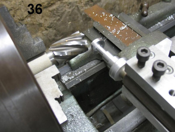
36 Milling 01
Remember that this part is only held fast by a 6mm thread which has a core of 5 mm and that the material is aluminum. The fact that the part is held at the base and cut at the top is also not to
your advantage as far as sturdiness at the cutting point is concerned. So I never make the cuts too deep. I always take my time and make several small cuts using low feeds.
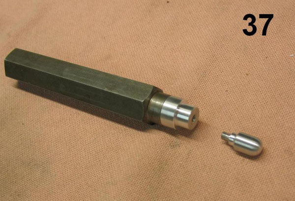
37 Adapter 02
This is the Blank for making Parts 1 and 2 in Sketch 24.

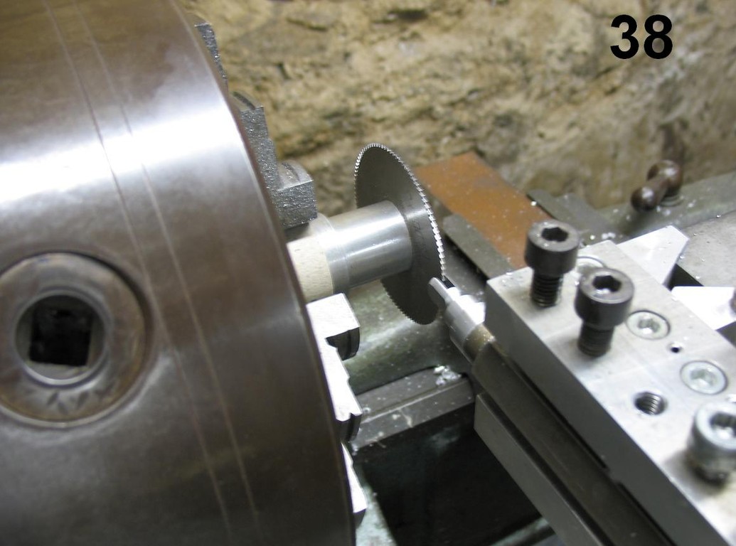
38 Milling 02
For milling this part I use a circular saw blade made of HSS ( High Speed Steel ) one millimeter thick. Again I make sure that the middle of the part to be cut is sitting higher than the
middle of the cutting tool ( 2 - 3 mm ).
The most critical cut is the first bite out of the middle. I tried several times to use ( even the slowest ) automatic feed for this cut and the result was always the same. At some time or
another an aluminum chip would get stuck between two of the cutting teeth, and the next time it came around it gouged into the blank causing it to break off at the thread. As a result:
I Never Use Automatic Feed When Performing This First Cut !!!! I Do It By Hand With Feeling Using Lots Of Cutting Fluid And Taking My Time !!!!
After this first cut I breath a little easier because any Build-Up now has a chance of yielding to the left or right rather than gouging Head-On into the Blank. I usually finish up taking
0.5mm bites at low feeds.
All of the other milling operations that I do on the lathe are in principle similar to these two examples using a specially built jig or adapter. My tip: Be creative, but be safe.
Making The Flywheel
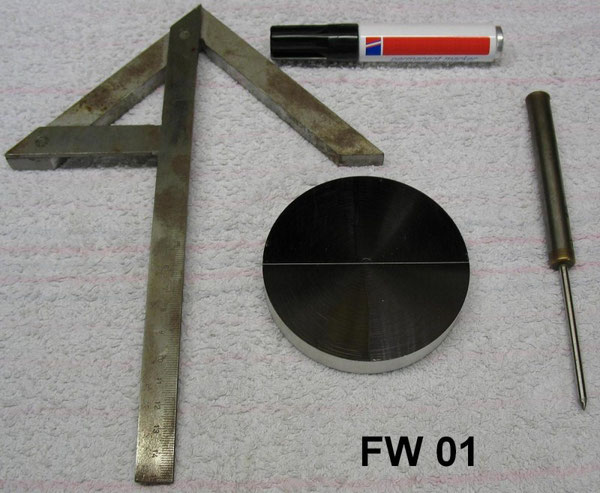
FW 01
In Pic FW 01 you can see the first step in making the Flywheel. The blank already has the finished diameter of 90mm, but I left the width about 0.2mm thicker. These two tenths of a mm will be
turned down later at the final cut.
After blackening the surface of the blank with a Permanent Marker ( there are special dyes for this purpose, but I´ve always had good enough results with standard felt-tipped markers ), draw a
line through the center using a Center Head ( I call it a Center Square ) and a Scriber.

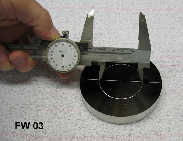
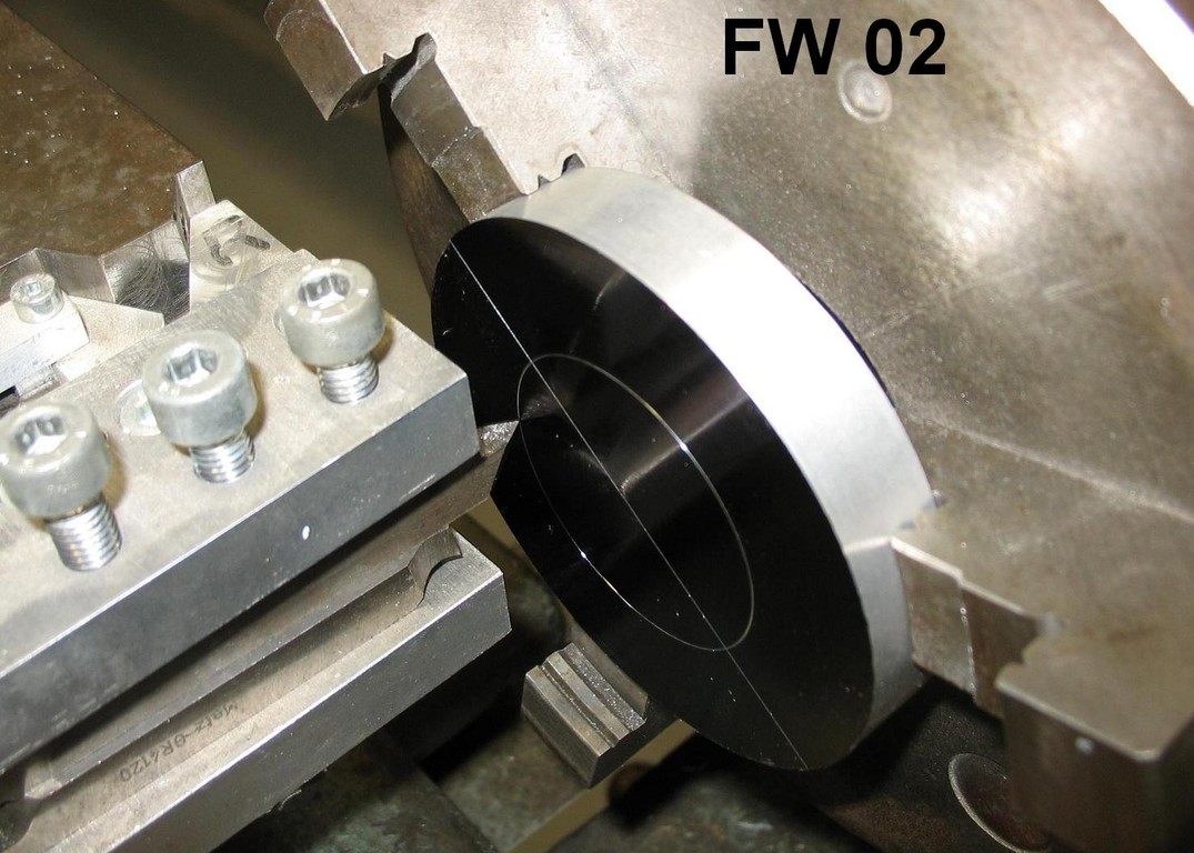
FW 02 + FW 03
I usually use a piece of scrap to find the setting for the circle diameter ( in this case 48mm ) using the following method:
1.) Scratch a circle about 2 or 3mm larger than the desired diameter.
2.) Measure the result along the center line and adjust for the difference.
3.) Scratch and measure again.
You should be pretty much on the money by now. If not, make another adjustment.
Now chuck up and scratch the blanc. Don´t scratch too deeply. My Standard scratch is 0.1mm.

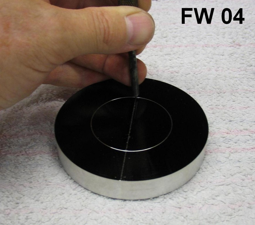
FW 04
Now make a light punchmark at one junction of the circle and center line

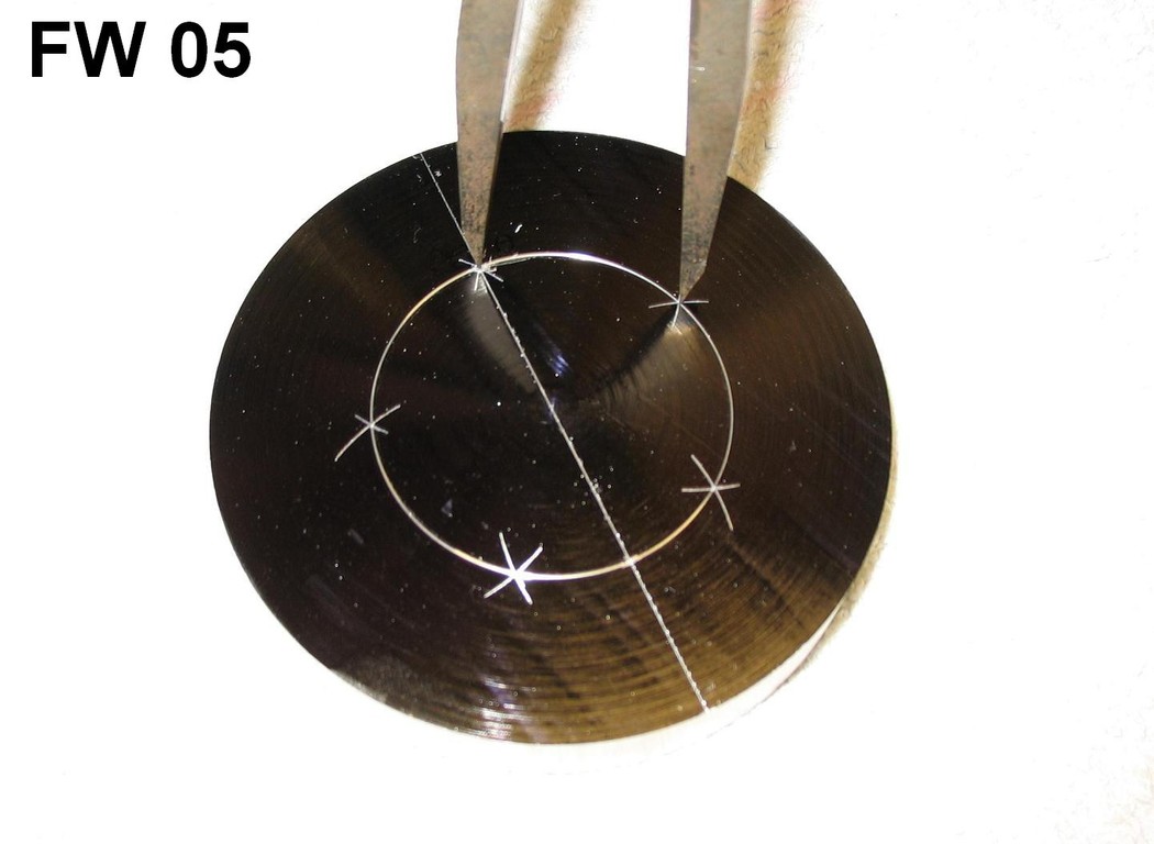
FW 05
Using a pair of ( very sharp ) dividers set at 28mm ( see sketch 26 ) walk around the circle. If at the fifth step the point of the divider hits the exact center of the punch mark, you are
in business. If not adjust the divider accordingly and try again. ( After scratching up the surface several times before getting the wanted results you may want to blacken the surface again
before making the final marks. )

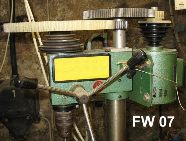
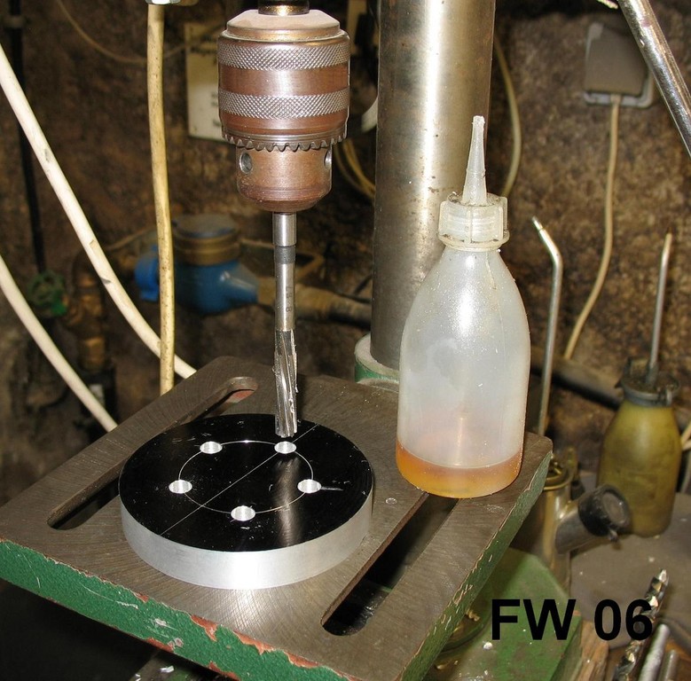
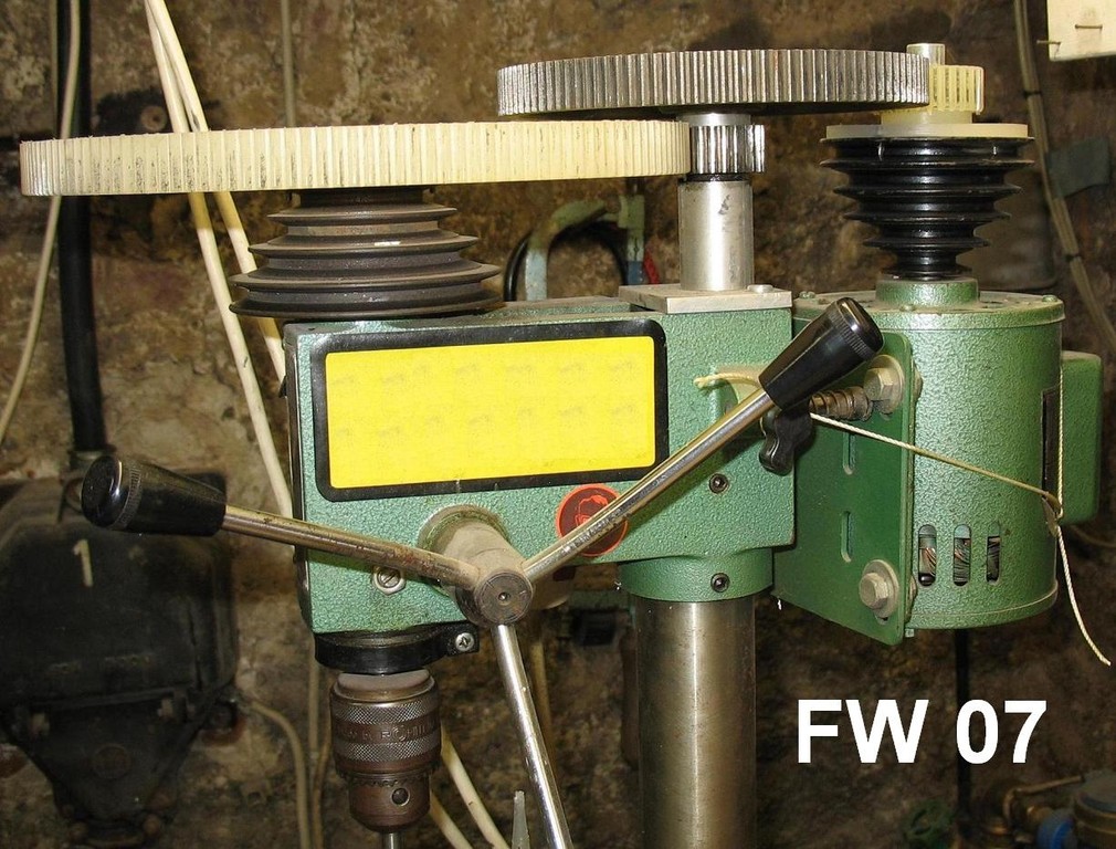
FW 06 + FW 07
After punching and pre-drilling with a center-drill and a regular twist-drill finish off with a reamer remembering to make a slip fit for the pins as stated earlier under `` Bushing ´´. I use an
8mm reamer, so the twist-drill has a diameter of 7,7mm. In FW 07 you can see how I´ve reduced the speed of my drill ( 64 RPM ) to accomodate reaming.
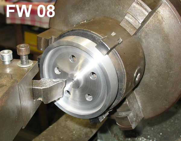
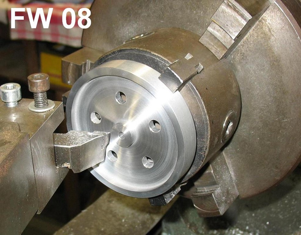
FW 08
Now turn the wheel to it´s final dimensions.
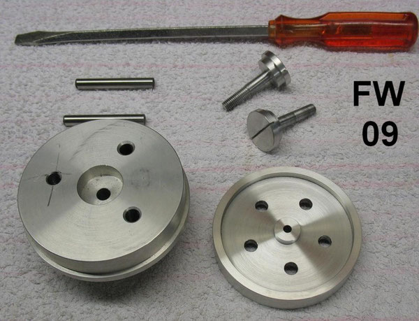
FW 09
Here you can see the adapter I use for turning the five 24mm holes in the wheel. This was a piece of scrap aluminum that had already had a hole drilled in it before, so just ignore the hole
to the left with an X through it. The center of the adapter has an 8mm hole reamed to a slip fit for the 8mm steel pin used for the center orientation of the 24mm holes to be turned. The screws
have 8mm and 24mm diameter sections to accommodate the clamping of the wheel in it´s different stages of turning.
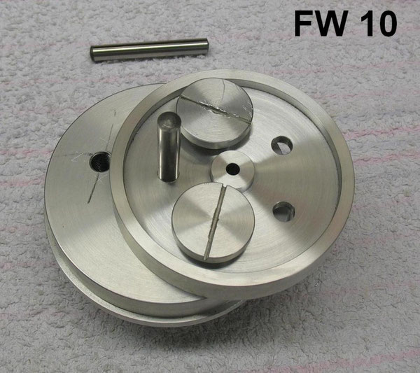
FW10
I used a ground 8mm steel pin to exactly position the the first hole over the center hole of the adapter. Then I marked, drilled and threaded the next two holes used for clamping the wheel in
place during turning.
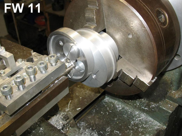
FW 11
After clamping the wheel in place and removing the steel pin the 24mm holes can now be turned on the lathe.

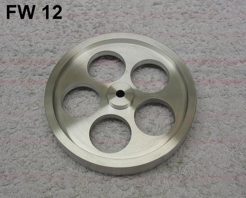
FW 12
The finished wheel. I use fine sand paper to deburr the holes and finish up the surface.
Running The Machine
It took me more than half an hour to get the machine running for the first time, and only after I realised that I had overtightened one or more of the connecting joints. So after loosening the
fastening screws a bit, applying a drop of light machine oil here and there and trying different ammounts of heat ( adjusting the height of the wick and the closeness of the flame to the test
tube ) it finally began to run at a rate of about 300 RPM´s. I still get a kick out of running it once in a while ( better than TV ).
Outro
I´ve been doing machine work ( mostly lathe and milling ) since 1983 and have always found it to be interesting and challenging. In short, I Just Love This Stuff !!!! Whether making a ( rare,
sometimes not to be found ) spare part for an Old Timer Tractor for the local farmer, or making modifications on the kids bikes or my 15 year old scooter, or something practical or
decorative for the household, I´ve always had fun with it. And that is what this is really all about, having fun. This is exactly the kind of stuff that our wise Forefathers had in mind when they
added the phrase `` PURSUIT OF HAPPINESS ´´ to our Declaration Of Independence. And so I wish you too all the fun you can possibly have in all your pursuits of
happiness.
Dave
Disclaimer
I have been machinig for over 30 years. And although there have been broken cutting tools and damaged parts ( this is a learning process and all machinists have experienced these things
), I have never had an accident which resulted in personal injury or machine damage. However, for safety reasons, I still cannot reccommend any of the Machining Practices represented in
this writing and the accompanying pictures. I only offer herewith a description of how I made this Stirling Motor.
If however you do decide to try any of the working methods described here, do so at your own risk and please use common sense and discretion and above all be safety oriented.
In applying any representations herein, you should exercise all care and normal precautions to prevent personal injury and damage to machines and facilities.
In no case can I accept responsibility for personal injury or damages which may occur in working with methods and / or materials described herein.
When doing any kind of work ( especially machining ), please use all recommended safety proceedures and equipment ( especially safety glasses ) at all times, and consider all
machine operations very carefully from a standpoint of safety before carrying them out. Also encourage your family, friends and colleagues to do the same.
Please use all reccommended safety proceedures when handling flammable materials.
Never let a machine like a stirling motor run unattended by an adult.
Never let children play with such machines ( these are not toys, they are working models of external combustion engines ).